.svg)
This Alternating Current Class 12 Notes PDF is made exactly for moments when the chapter feels overwhelming and time is short. The notes focus on NCERT-aligned concepts, so you don’t feel lost in derivations or messy graphs.
You can revise directly on your phone, re-read key ideas just before the exam, or use it for last-minute panic preparation without opening multiple books. Every important concept is explained in a simple, board-friendly way, with emphasis on why things happen
What is Alternating Current?
Alternating Current (AC) is an electric current whose magnitude and direction change periodically with time.
Mathematical representation ⇒ i(t) = I₀ sin(ωt) and v(t) = V₀ sin(ωt), where
- I₀ = Peak current
- V₀ = Peak voltage
- ω = Angular frequency = 2πf
- f = Frequency
AC is preferred over DC because it can be stepped up or down using transformers, making long-distance transmission efficient.
Average Value of AC
For a complete cycle ⇒ Average value of AC = 0 (because positive and negative halves cancel each other)
So instead, we calculate average over half cycle Iavg = 2I0/π
However, average value is not practically useful. Therefore, RMS value is used.
RMS Value of Alternating Current
RMS (Root Mean Square) value of AC is the effective value of current or voltage that produces the same heating effect as DC.
Irms = I0/√2 and Vrms = V0/√2
So for example, if household supply is 220 V, it means 220 V (RMS).
Relation between peak and RMS ⇒ L₀ = √2 Lrms and V₀ = √2 Vrms
AC Through a Pure Resistor
In a resistor:
- Voltage and current are in phase
- Both reach maximum and zero at the same time
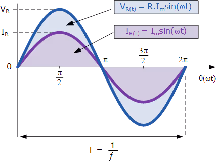
Graphically:
- Peaks coincide
- No phase difference
Power ⇒ P = VI
Power is always positive → energy is continuously consumed as heat.
Derivation:
Applied voltage ⇒ v = V0sin(ωt)
Current ⇒ i = (V0/R) sin(ωt)
Since ⇒ I0 = V0 / R
Phase relation ⇒ Voltage and current are in phase (φ = 0)
Average power consumed ⇒ Pavg = Vrms Lrms
Since cosφ = 1 for resistor ⇒ Pavg = Vrms Lrms cosφ
Power is always positive → energy is continuously dissipated as heat.
AC Through a Pure Inductor
An inductor resists change in current by storing energy in its magnetic field. So, current lags behind voltage by 90°
Inductive reactance ⇒ XL = ωL
Points to Remember:
- Higher frequency → higher opposition
- No power loss (ideal inductor)
Derivation:
Voltage-current relation ⇒ V = L (di/ dt)
Current ⇒ i = I0 sin(ωt − π/2)
Phase relation ⇒ Current lags voltage by 90° (π/2)
Inductive reactance ⇒ XL = ωL
Current amplitude ⇒ I0 = V0 / XL
Average power ⇒ Pavg = Vrms Lrms cos90° ⇒ Pavg = 0
Thus, no average power is consumed. This is called wattless current.
AC Through a Pure Capacitor
A capacitor stores charge and releases it quickly. So, current leads voltage by 90°
Capacitive reactance ⇒ XC = 1/ωC
Important points:
- Higher frequency → less opposition
- No power loss (ideal capacitor)
Derivation:
Current-voltage relation ⇒ i = C (dV/ dt)
Current ⇒ i = I0 sin(ωt + π/2)
Phase relation ⇒ Current leads voltage by 90° (π/2)
Capacitive reactance ⇒ XC = 1 / (ωC)
Current amplitude ⇒ I0 = V0 / XC
Average power ⇒ Pavg = Vrms Lrms cos90° = 0
Thus, the capacitor also consumes no average power (wattless current).
LCR Series Circuit
When R, L, and C are connected in series, opposition to AC is called impedance (Z).
Phase difference ⇒ Z = √(R2 + (XL – XC)2
Current ⇒ I0 = V0 / Z
Phase angle ⇒ tan Φ = (XL – XC)/R
- If XL > XC: current lags
- If XC > XL: current leads
Resonance in LCR Circuit (Very Important)
Resonance occurs when ⇒ XL = XC
ω0 L = 1 / (ω0C)
Resonant angular frequency ⇒ ω0 = 1 / √(LC)
Resonant frequency ⇒ f0 = 1 / (2π√LC)
At resonance:
- Impedance Z = R (minimum)
- Current is maximum
- Power factor = 1
- Circuit behaves like pure resistor
Used in:
- Radio tuning
- TV receivers
- Communication systems
Power in AC Circuits - Very Important
Instantaneous power ⇒ P = v i
Average power ⇒ Pavg = Vrms Lrms cosφ, where cosφ is called power factor.
Power factor ⇒ cosφ = R / Z
Cases:
- Pure resistor → cosφ = 1 → maximum power
- Pure inductor/capacitor → cosφ = 0 → zero average power
Industries use capacitors to improve power factor.
LC Oscillations
In an LC circuit, energy oscillates between the electric field of the capacitor, and the magnetic field of the inductor. Total energy remains constant in an ideal LC circuit.
Quality Factor (Q-Factor)
Quality factor of LCR circuit ⇒ Q = ω0L / R; It measures sharpness of resonance.
- Higher Q → sharper resonance
- Lower Q → broader resonance
Transformer - Application of AC
A transformer works only on AC. Principle ⇒ Mutual induction
Turns ratio ⇒ Vs/Vp = Ns/Np, where Vs = Secondary voltage; Vp = Primary voltage; Ns = Secondary turns; and Np = Primary turns
- For ideal transformer ⇒ Vp Lp = Vs Ls
- Step-up transformer ⇒ Ns > Np → increases voltage
- Step-down transformer ⇒ Ns < Np → decreases voltage
Used in:
- Power transmission
- Chargers
- Adapters
FAQs
1. What is alternating current in Class 12 Physics?
Ans. Alternating current (AC) is an electric current whose magnitude and direction change periodically with time. It is represented as ⇒ i = I0 sin(ωt)
2. What is the formula for the RMS value of AC?
Ans. The RMS value of current and voltage is ⇒ Irms = I0/√2 and Vrms = V0/√2. RMS value represents the effective value of AC equivalent to DC in terms of heating effect.
3. Why is the average value of AC zero?
Ans. The average value of AC over one complete cycle is zero because the positive and negative halves of the sine wave cancel each other.
4. What is impedance in an LCR circuit?
Ans. Impedance (Z) is the total opposition offered to AC in a circuit containing resistance, inductance, and capacitance. Z = √[R2 + (XL − XC)²]. It combines resistance and reactance.
5. What is the resonance condition in an LCR circuit?
Ans. Resonance occurs when ⇒ XL = XC; Resonant frequency ⇒ f0 = 1 / (2π√LC)/ At resonance, impedance is minimum, current is maximum, and power factor is 1.
6. What is the power factor in AC circuits?
Ans. Power factor is defined as ⇒ cosφ = R / Z. It indicates how effectively electrical power is being converted into useful work. For a pure resistor, power factor = 1. For a pure inductor or capacitor, power factor = 0.
7. Why is power zero in a pure inductor or capacitor?
Ans. In a pure inductor or capacitor, the phase difference between voltage and current is 90°. Since: Pavg = Vrms Lrms cos90° ⇒ Pavg = 0. No average power is consumed. This is called wattless current.